
Views: 7 Author: Monica Publish Time: 2026-01-16 Origin: Site


JN ALLOY shipped 153 pieces of ASTM A182 F53 (UNS S32750) super duplex weld neck flanges to Argentina for oil and gas service in the Vaca Muerta basin. Every piece is ASME Class 150, spans 6 in to 26 in NPS, and was supplied solution annealed and water quenched with EN 10204 3.1 certification.
F53 was chosen because Vaca Muerta flowback reaches seawater salinity within a month and parts of the basin carry hydrogen sulphide. That combination puts carbon steel and 316L outside their safe limits, while F53 - with a PREN of 40 or higher and a 550 MPa minimum yield - stays inside its envelope at a fraction of the cost of a nickel alloy.
Item | Detail |
Shipment | 153 pieces of ASTM A182 F53 (UNS S32750) weld neck flanges |
Destination | Argentina - Neuquen Basin / Vaca Muerta supply chain |
Inquiry received | December 2025 |
Pressure class | ASME Class 150 throughout |
Size range | 6 in to 26 in NPS |
Facings | Flat face (FF) and raised face (RF) |
Material group | ASME B16.5 / B16.47 Material Group 2.8 (25Cr-7Ni-4Mo-N) |
Designation | F53 / UNS S32750 / EN 1.4410 / X2CrNiMoN25-7-4 / alloy 2507 |
PREN | >=40 (Cr + 3.3 x Mo + 16 x N); typical 41-43 |
Minimum yield | 550 MPa (80 ksi) solution annealed |
Heat treatment | Solution anneal >=1025 C (1880 F) + water quench; PWHT prohibited |
Service window | -30 C to +315 C (-20 F to 600 F) for ASME B16.5 use |
Certification | EN 10204 3.1 mill certificate, heat-code traceability |
Sour service | NACE MR0175 / ISO 15156-3 - limit must be stated on the PO |
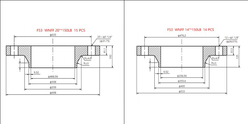
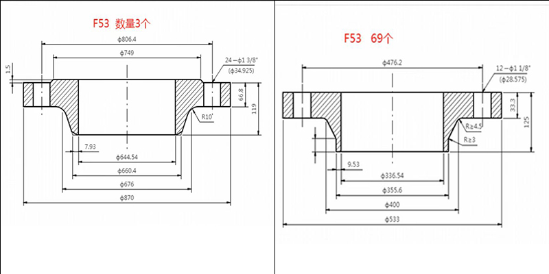
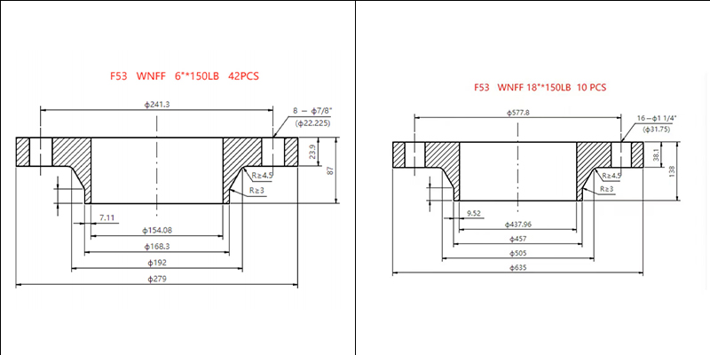
In December 2025 JN ALLOY received an inquiry from an Argentine procurement officer working on oil and gas development who needed a large quantity of weld neck flanges able to survive seawater and hydrogen sulphide. The order that followed - 153 pieces of F53 (UNS S32750) super duplex weld neck flanges in sizes from 6 in to 26 in, all ASME Class 150 - is a useful case study in how a country's geology ends up dictating a metallurgical specification.
This page records what was shipped, why F53 was the right grade for it, which standards the 153 pieces were built to, and what an Argentine or international buyer should write on a purchase order to get the same result. Every number below is traceable to a published standard or a named source, and where a figure depends on which edition of a standard you work to, this page says so rather than picking one.
NOTE: In short: 153 F53 (UNS S32750) weld neck flanges, ASME Class 150, 6 in to 26 in, flat and raised face, manufactured to ASME B16.5 and ASME B16.47, solution annealed and water quenched, shipped with EN 10204 3.1 certification and full heat-code traceability. The grade was chosen because Vaca Muerta flowback reaches seawater salinity within weeks and carries H2S - conditions that rule out carbon steel and 316L.
153 pieces of ASTM A182 F53 (UNS S32750) weld neck flanges, all ASME Class 150, spanning 6 in to 26 in NPS, in flat face and raised face, supplied solution annealed and water quenched with EN 10204 3.1 certification.
The table below reproduces the original order line exactly as recorded on this page when it was published. It is kept unchanged so the shipment record stays auditable.
The order as recorded at the time of shipment (reproduced unchanged)
Product | Description | Quantity |
Grade | F53/UNS S32750 | |
WN Flanges | 14 inch 150FF | 69 PCS |
WN Flanges | 26 inch 150 RF | 3 PCS |
WN Flanges | 18 inch 150LB | 10 PCS |
WN Flanges | FF 6 inch 150LB | 42 PCS |
WN Flanges | FF 20 inch 150LB | 15 PCS |
WN Flanges | FF 14 inch 150LB | 14 PCS |
Adding the quantities gives 69 + 3 + 10 + 42 + 15 + 14 = 153 pieces, which matches the headline. Two details are worth reading carefully before you reuse this as a template.
First, the 26 in item cannot be an ASME B16.5 flange: B16.5 stops at NPS 24, so that piece is built to ASME B16.47. Second, 14 in appears twice, once as a flat-face item of 69 pieces and once as a flat-face 150 lb item of 14 pieces - either two distinct 14 in lines with different bores or schedules, or a duplicated entry. Both are flagged for the sales record rather than silently corrected here.
Reading the order: what each line tells you
Size | Facing | Class | Quantity | What the configuration implies |
6 in | FF | 150 | 42 pcs | Small-bore branch and utility lines; flat face usually means a non-metallic or cast mating item |
14 in | FF | 150 | 69 pcs | The volume line of the order - a main header or manifold in flat face |
14 in | FF | 150 lb | 14 pcs | Second 14 in line - confirm bore and schedule against the first |
18 in | 150 lb | 150 | 10 pcs | Large-bore header; faces as recorded on the original order |
20 in | FF | 150 lb | 15 pcs | Large-bore flat face, typical of water and low-pressure gathering service |
26 in | RF | 150 | 3 pcs | Above the B16.5 size limit - must be ASME B16.47 Series A or Series B |
Because Vaca Muerta has turned Argentina into one of the fastest-growing upstream markets outside North America, and the fluids it produces are aggressive. More than 90 per cent of the country's 2026 upstream capital budget is directed at that one formation, and every barrel and every cubic metre of water moved there needs pipe, flanges and fittings.
Argentina's crude output passed its 1998 record in October 2025 at 859,500 barrels per day, with the Neuquen Basin contributing more than 653,000 b/d - about 69 per cent of national supply. Neuquen province alone produced 587,190 b/d that month, up 31 per cent year on year, and the basin's shale oil climbed to a record 622,700 b/d by May 2026, an increase of 39 per cent on the previous year. Hydraulic fracturing activity grew in step: 23,896 fracture stages were completed in 2025, 34 per cent more than in 2024, with more than 28,000 projected for 2026.
Those numbers matter to a flange buyer for a simple reason. Unconventional development is not one big pipeline - it is hundreds of wells, each with gathering lines, manifolds, water transfer, disposal and treatment connections. Surface facilities scale with well count, and every one of those connections is a flange. When an operator adds a pad, the flange order grows with it. Less than 10 per cent of the Vaca Muerta formation has been developed so far, so the surface-facility build-out has years to run.
Two construction programmes amplify the effect. The Oldelval trunkline expansion raised crude takeaway capacity from 225,000 to 540,000 b/d, and the Vaca Muerta Oil Sur (VMOS) export system is expected online in early 2027 with the potential to ramp towards 700,000 b/d by 2028. Large-diameter, low-to-moderate pressure piping is exactly what Class 150 flanges in the 14 in to 26 in range are for - which is what this order consists of.
Vaca Muerta is a Late Jurassic to Early Cretaceous shale formation about 2,900 m beneath the Neuquen Basin of northern Patagonia. It covers roughly 30,000 square kilometres, supplies around 70 per cent of Argentina's crude and about 80 per cent of Neuquen's gas, and is the largest producing shale play outside North America.
The scale is why it changes procurement patterns. The US Energy Information Administration ranks Argentina as holding the world's second-largest shale gas resources and fourth-largest shale oil resources. Wood Mackenzie describes Vaca Muerta production as just under 0.9 million barrels of oil equivalent per day and forecasts it rising beyond 1.6 million boe/d by 2035, with breakevens in the sweet spots comparable to the best US plays. The RIGI large-investment regime introduced in 2024 reduced corporate tax, removed export duties and exempted imported capital goods from tariffs and VAT, which is why the investment pipeline now runs well past US$100 billion.
Vaca Muerta at a glance
Metric | Value | Reference point |
Location | Neuquen Basin, northern Patagonia, Argentina | Mainly Neuquen province |
Formation age | Late Jurassic to Early Cretaceous marl and black shale | Depth about 2,900 m |
Area | About 30,000 km2 | Less than 10 % developed |
Share of national crude | About 70 % | Shale is about 80 % of Neuquen gas |
Argentina crude output | 859,500 b/d, October 2025 | Record; previous record 847,000 b/d in 1998 |
Neuquen shale oil | 653,000 b/d, October 2025; 622,700 b/d, May 2026 | +39 % year on year in May 2026 |
Fracture stages | 23,896 in 2025; more than 28,000 projected for 2026 | +34 % year on year |
2026 upstream budget | US$13.89 bn total, US$12.37 bn to Vaca Muerta | About 91 % of sector spend |
Takeaway capacity | Oldelval 225,000 to 540,000 b/d; VMOS from early 2027 | VMOS could ramp to about 700,000 b/d by 2028 |
Global resource ranking | 2nd-largest shale gas, 4th-largest shale oil | US EIA assessment |
Salinity. Measured Vaca Muerta flowback rises from about 2,000 mg/L total dissolved solids to more than 43,000 mg/L within a month - saltier than seawater - and the disposal-zone brines beneath the formation are more saline still. Add H2S in parts of the basin and carbon steel and 316L fall outside their safe envelope.
This is the part of the story that most material pages skip, and it is the reason for the grade choice. A 2023 study of a hydraulically fractured Vaca Muerta well, published in Geoenergy Science and Engineering by Osselin and colleagues from the Universite d'Orleans, BRGM, TotalEnergies and the University of Calgary, sampled the fracture fluid, coil-tubing returns, flowback and produced water. Total dissolved solids rose by more than an order of magnitude during the operation: roughly 1,500 mg/L in the injected fracture fluid, 13,978 mg/L mid-way through coil tubing, 23,824 mg/L at the end of coil tubing, and about 43,000 mg/L a month later as formation water mixed in.
For comparison, seawater is about 35,000 mg/L total dissolved solids. In other words, water that starts out nearly fresh reaches seawater salinity - and beyond - inside a month of contact with the formation. Shell's geochemical baseline work in the Neuquen Basin found the same pattern from a different direction: the Centenario disposal zone is described as very saline, several times seawater and more saline than Vaca Muerta produced water itself, while shallow monitor zones such as the Rayoso are generally below 5,000 mg/L.
Salt is only half the problem. YPF's work on produced-water reuse records that all fracturing water in the formation is currently sourced from surface water and all recovered water is injected into disposal wells, which means very large volumes of saline water are moved, stored and re-injected continuously. Where H2S is present in the stream, the two mechanisms - chloride pitting and sulphide stress cracking - act together, and that combination is what eliminates most low-alloy and standard-stainless options.
Salinity of the water cycle in Vaca Muerta operations
Stream | Total dissolved solids | Why it matters for materials |
Fracture make-up water | About 1,500-2,000 mg/L | Mild; carbon steel survives with treatment and inhibition |
Coil-tubing returns | 13,978 to 23,824 mg/L | Approaching brackish to seawater; 316L pitting risk becomes real |
Flowback after one month | About 43,000 mg/L | Above seawater salinity; needs PREN 40 class materials |
Centenario disposal-zone brine | Several times seawater | Disposal and injection systems need the highest tier of the stainless ladder |
Rayoso monitor zone | Generally below 5,000 mg/L | Fresh baseline used to detect cross-formation migration |
Seawater (reference) | About 35,000 mg/L | The usual benchmark for the PREN 40 threshold |
NOTE: Source note: the 43,000 mg/L figure is a single-well measurement from a published study, not a basin-wide average. Treat it as an order-of-magnitude indicator of how fast salinity climbs, and test your own produced water before finalising a material selection.
Because the service sits above the line where 316L cracks and above the line where standard duplex runs out of margin. F53 clears PREN 40, the threshold most chloride and offshore specifications use, while 316L sits in the mid-20s and 2205 sits around 34 to 36.
Material selection in this kind of service is not about picking the best alloy - it is about matching the alloy's envelope to the actual fluid. Three variables drive the decision: how much chloride is present, how hot the metal runs, and whether H2S is in the stream. Move any one of those up and the ladder moves with it. The Argentine buyer's brief named seawater and hydrogen sulphide, which places the service in the upper half of the ladder immediately.
PREN is the quickest way to see why. It weights the three elements that resist chloride pitting - chromium, molybdenum and nitrogen - into one number. Each rung of the stainless ladder corresponds to a jump in that number, and each jump buys a real increase in the temperature and salinity the material tolerates.
The PREN ladder: where each grade stops working
Grade | UNS | PREN (typical) | Minimum yield | Where it runs out |
316L | S31603 | Mid-20s | About 170 MPa | Chloride stress corrosion cracking above roughly 60 C; pitting in seawater |
Duplex 2205 (F51 / F60) | S31803 / S32205 | 34-36 | 450 MPa | Warm seawater, crevice conditions, high-chloride brine at temperature |
Super duplex 2507 (F53) | S32750 | 41-43 | 550 MPa | Above about 315 C by embrittlement, or when H2S exceeds the qualified envelope |
Super duplex F55 | S32760 | About 40+ | 550 MPa | Same tier as F53; chosen where tungsten and copper add acid resistance |
254 SMO | S31254 | About 42 | About 300 MPa | Excellent pitting resistance but much lower strength than super duplex |
Inconel 625 | N06625 | About 45-50 | About 415 MPa (annealed) | Cost; used where chloride, sour severity or temperature exceed super duplex |
Two things follow from that table. The first is that F53 is not the top of the ladder - it is the point where corrosion resistance and strength arrive together at a defensible price. A super austenitic such as 254 SMO matches it on pitting resistance but gives roughly half the yield strength, which means thicker sections and heavier flanges for the same duty. The second is that going below F53 is a genuine risk, not a saving: a 316L flange in 43,000 mg/L chloride water is a scheduled failure, and a 2205 flange in warm, H2S-bearing brine has very little margin left.
If you want to read the full grade data before specifying, the super duplex S32750 grade page carries the composition, mechanical and product-form detail, and the duplex and super duplex overview sets F53 against the rest of the family.
F53 gives close to nickel-alloy corrosion resistance at roughly half the material cost, with more than three times the yield strength of 316L. It loses to Inconel 625 and Hastelloy C276 only where chloride, H2S severity or temperature exceed the super duplex envelope - or where elemental sulphur is present, which duplex grades do not qualify for.
Selection comparison for Class 150 corrosive-service flanges
Option | Strength | Chloride resistance | Sour (H2S) position | Relative cost | Choose it when |
ASTM A105 carbon steel | 250 MPa yield | None - needs inhibition | Not qualified bare | 1x | Dry, inhibited, non-saline utility service only |
316L (F316L) | About 170 MPa yield | PREN mid-20s | Narrow; SCC risk above about 60 C | 2-3x | Low chloride, low temperature, short design life |
Duplex 2205 (F51 / F60) | 450 MPa yield | PREN 34-36 | Listed; roughly 2 kPa H2S class envelope | 3-4x | Moderate chloride, ambient seawater, no H2S or very low H2S |
Super duplex F53 (S32750) | 550 MPa yield | PREN 41-43 | Listed; much wider envelope than 22Cr duplex | 4-5x | Warm saline water, produced water, seawater, moderate H2S |
Super duplex F55 (S32760) | 550 MPa yield | PREN 40+ | Listed, similar to F53 | 4-6x | Where W and Cu help against acid or where a UK heritage spec calls it |
254 SMO (F44) | About 300 MPa yield | PREN about 42 | Listed; used for its pitting margin | 5-7x | Where pitting margin dominates and strength does not |
Inconel 625 (N06625) | About 415 MPa yield | PREN about 45-50 | Wide; also covers elemental sulphur | 10x+ | Severe sour, high temperature, or where the duplex envelope is exceeded |
Read the cost column with care. Those are indicative multiples per kilogram for the alloy, not flange prices, and they move with nickel and molybdenum markets. The correct comparison is cost per year of service, and in a saline, H2S-bearing line the multiplier on life is usually far larger than the multiplier on price.
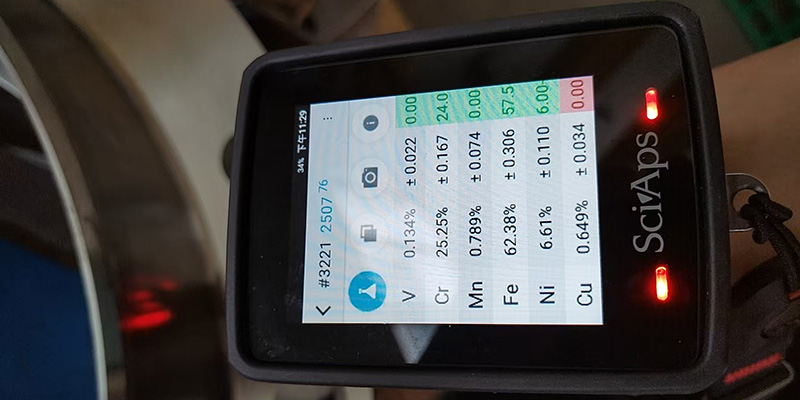
ASTM A182 F53 requires 24-26 % chromium, 6-8 % nickel, 3-5 % molybdenum and 0.24-0.32 % nitrogen, with a maximum of 0.030 % carbon. In the solution annealed condition the minimum tensile strength is 800 MPa, minimum 0.2 % yield 550 MPa, minimum elongation 15 % and maximum hardness 310 HBW.
Nitrogen is the element that separates super duplex from duplex, and it earns its place twice. It contributes sixteen times its percentage to the PREN calculation, and it stabilises the austenite phase so the richer chromium and molybdenum do not push the microstructure too far towards ferrite. The carbon ceiling is equally deliberate: keeping carbon at 0.030 % or below limits chromium carbide precipitation during welding.
ASTM A182 F53 chemical composition limits (UNS S32750)
Element | Requirement | Role in the alloy |
Chromium | 24.0-26.0 % | Passive film formation; the base of PREN |
Nickel | 6.0-8.0 % | Stabilises austenite; underpins toughness |
Molybdenum | 3.0-5.0 % | Pitting and crevice resistance; 3.3x weight in PREN |
Nitrogen | 0.24-0.32 % | Strength plus 16x weight in PREN; the super element |
Manganese | 1.20 % max. | Deoxidiser; kept low to limit intermetallics |
Silicon | 0.80 % max. | Deoxidiser; kept low for the same reason |
Carbon | 0.030 % max. | Low to prevent chromium carbide sensitisation |
Phosphorus / sulphur | 0.035 / 0.020 % max. | Impurities; kept low for toughness and weldability |
Copper | 0.50 % max. | Residual in F53; a deliberate addition in F55 |
Iron | Balance | Matrix |
ASTM A182 F53 mechanical and heat-treatment requirements
Property | Requirement | Note |
Tensile strength, minimum | 800 MPa (116 ksi) | Room temperature, solution annealed |
0.2 % yield strength, minimum | 550 MPa (80 ksi) | About 2.7x the yield of 316L |
Elongation, minimum | 15 % | The usual price of the higher strength |
Hardness, maximum | 310 HBW (about 32 HRC) | Sour-service orders often tighten this to 28 HRC - state it on the PO |
Impact toughness | Commonly 45 J at -46 C | A project requirement rather than an A182 default; specify if needed |
Ferrite content | Typically 40-60 % | Verified by point count or magnetic measurement where specified |
Solution anneal | 1025-1125 C, water quench | Mandatory and furnace-documented; no field heating permitted |
Post-weld heat treatment | Prohibited | Falls in the sigma and 475 C embrittlement range |
Intermetallic-phase check | ASTM A923 Methods A, B, C where specified | The standard check for sigma and chi phase |
Pitting check | ASTM G48 Method A where specified | Critical pitting temperature well above 2205 |
NOTE: ASTM A182 publishes size- and thickness-dependent minima for some product forms, so the exact tensile and yield figures for a heavy hub forging can differ from the values above. Read them from the edition named on your purchase order rather than from any summary, including this one.
ASME B16.5 governs every line up to 24 in; the 26 in line is governed by ASME B16.47 instead. B16.5 stops at NPS 24, so anything larger must be built to B16.47 Series A (MSS SP-44 lineage) or Series B (API 605 lineage) - and the two series are not interchangeable.
This is the most common specification error in large-diameter orders, and it is easy to make because the two standards look interchangeable on a datasheet. They are not. Series A flanges are heavier, use larger and more numerous bolts, and are preferred where external loads are high. Series B flanges are lighter, cheaper and common in cost-sensitive transmission and retrofit work. Their bolt circles differ, so a Series A flange will not bolt to a Series B flange of the same size and class. Series A does align with B16.5 at the NPS 24 to 26 boundary, which is often why it is chosen for mixed systems.
Flange standard coverage for this order
Standard | Size range | Classes | Relevant to this shipment |
ASME B16.5 | NPS 1/2 to NPS 24 | 150 to 2500 | Covers the 6, 14, 18 and 20 in lines; F53 sits in Material Group 2.8 |
ASME B16.47 Series A (MSS SP-44) | NPS 26 to NPS 60 | 150 to 900 | Candidate for the 26 in line; heavier, higher external-load capacity |
ASME B16.47 Series B (API 605) | NPS 26 to NPS 60 | 75 to 900 | Candidate for the 26 in line; lighter and more economical |
ASME B31.3 / B31.4 / B31.8 | System design codes | - | Determine the piping class that selects the flange in the first place |
ASME B16.5 temperature limits for F53 | - | - | Maximum 600 F (315 C); minimum -20 F (-30 C) without impact testing |
F53 is listed in Material Group 2.8 of both B16.5 and B16.47, alongside F44, F51 and F55. That matters because the pressure-temperature rating is set by the material group, not by the alloy name, so the Class 150 rating for an F53 flange is read from the Group 2.8 table in the edition you are working to. It also places a hard ceiling on the alloy: B16.5 does not permit F53 above 600 F (315 C), because sigma phase and 475 C embrittlement take over in that range.
Because the tapered hub moves stress away from the weld, the butt joint can be fully radiographed, and the smooth bore resists erosion and turbulence in a corrosive, solids-bearing fluid. For chloride and H2S service at Class 150 on 6 to 26 inch lines, a weld neck is the conservative choice and usually the Code-preferred one.
The geometry does the work. A slip-on flange is fillet welded on both sides, which leaves a crevice at the bore and puts the weld in the highest-stress region; a weld neck is butt welded to the pipe so the hub thickness tapers down to match the pipe wall, carrying the bending load smoothly into the pipe. In a cyclic service - and gathering and water systems cycle constantly with pad operations - that difference is the difference between a flange that lasts and one that cracks at the hub-to-pipe transition.
Flange type selection for corrosive hydrocarbon and water service
Type | Joint | Best for | Why not here |
Weld neck (WN) | Butt weld, radiographable | High pressure, cyclic load, corrosive and elevated-temperature service | Chosen for all 153 pieces |
Slip-on (SO) | Two fillet welds | Low-pressure, non-cyclic, easy fit-up | Crevice at the bore and a lower fatigue rating |
Socket weld (SW) | Fillet weld in a socket | Small bore, NPS 2 and below | Size limit and a crevice that traps chloride |
Blind (BL) | Bolts only, no bore | Line termination and future tie-ins | Different function - not a pipe connector |
Lap joint (LJ) | Stub end plus loose ring | Frequent dismantling, or expensive piping with cheap rings | Lower fatigue strength and a crevice under the ring |
If you are specifying the rest of the piping class to match, the weld neck flange product page covers sizes and classes we run regularly, and the weld neck flange guide goes through hub dimensions, bore matching and facing options in more detail.
FF is flat face and RF is raised face. The order mixes both: five of the six lines are flat face, which usually means those lines mate to cast, GRP or non-metallic equipment, while the 26 in line is raised face, the default for steel-to-steel process piping.
The distinction is not cosmetic, and getting it wrong is one of the few installation errors that can damage a flange the first time it is bolted up. A raised face concentrates the entire bolt load onto a narrow gasket ring, which gives high seating stress and a reliable seal against a rigid steel partner. A flat face spreads that load across the whole sealing area because the partner cannot take the concentrated load without bending or cracking. Bolt an RF flange to an FF flange and the raised ring will lever the flat-face partner until it distorts or cracks.
Facing selection for Class 150 super duplex flanges
Facing | Sealing area | Typical partner | Gasket | Caution |
Raised face (RF) | Raised concentric ring, commonly 1.6 or 6.4 mm | Steel flange or steel valve | Spiral wound, PTFE or compliant sheet | Never bolt to a flat-face partner |
Flat face (FF) | Full face machined flat | Cast iron, GRP, FRP, non-metallic or lined equipment | Full-face soft gasket | Bolt load is spread, so gasket seating stress is lower |
Ring type joint (RTJ) | Machined groove holding a metal ring | High-pressure and critical hydrocarbon service | Soft iron or stainless ring | Not used on Class 150 in this order; needs a harder facing |
Because this order mixes the two, the installer's first job is to match each flange to its partner before it reaches the welding bay. Face type, class and bore should all be read off the marking on the flange hub and checked against the line list - not assumed from the packing list.
Yes, conditionally. UNS S32750 is listed in NACE MR0175 / ISO 15156-3, but qualification is conditional on three things: the material must be solution annealed and water quenched, it must meet the hardness limit your specification sets, and the service must fall inside the published envelope for H2S partial pressure, chloride, pH and temperature.
That word 'conditionally' carries real weight, and it is where most misunderstandings start. Being a listed material is not the same as being qualified for your well. The standard gives each alloy family an environmental envelope defined by four variables, and a flange that is perfectly compliant on paper can still be outside its envelope on one of them. Super duplex tolerates substantially more H2S than 22Cr duplex, but it is not unlimited, and the standard does not qualify duplex grades at all where elemental sulphur is present - that service needs a nickel alloy.
There is also a documentation trap worth naming. The hardness limit quoted for S32750 differs between sources: the ASTM product specification permits up to 310 HBW, which is about 32 HRC, while many operator specifications - Shell DEP and Saudi Aramco SAES among them - tighten it to 28 HRC and apply it to base metal, weld metal and heat-affected zone alike. Neither figure is wrong; they answer different questions. The binding one is the figure in your project specification, and it has to be written on the purchase order.
What to state on the PO when H2S is present
Item | What to write | Why it cannot be left open |
Standard | NACE MR0175 / ISO 15156-3 and the edition | Envelopes and listed grades change between editions |
Hardness | Maximum HRC or HBW, and where it is measured | Product spec and operator spec differ; 32 HRC vs 28 HRC is a real gap |
Condition | Solution annealed and water quenched, furnace chart attached | The listed condition is not optional - it is part of the qualification |
H2S partial pressure | Value in kPa or psi | The envelope is expressed as partial pressure, not concentration |
Chloride concentration | mg/L or weight % | Sets the envelope together with pH and temperature |
In-situ pH and temperature | Measured or estimated values | Two of the four envelope variables |
Elemental sulphur | Present or absent | Duplex grades are not qualified where elemental sulphur is present |
Testing | NACE TM0177 or TM0316 if the service is near the limit | Demonstrates fitness rather than assuming it |
NOTE: NACE MR0175 / ISO 15156 addresses cracking only - sulphide stress cracking, stress corrosion cracking and galvanically induced hydrogen stress cracking. Pitting, crevice corrosion and general corrosion are assessed separately through PREN, ASTM G48 data and testing against your own produced fluid. A material can pass the cracking standard and still corrode away.
By hot forging a solution-annealed billet, rough machining, solution annealing at 1025-1125 C with a water quench, finish machining to ASME dimensions, and then verifying chemistry, mechanical properties, hardness, dimensions and identity piece by piece before release. The heat treatment is the step that makes or breaks the alloy.
The metallurgical reason is straightforward once you see it. Super duplex carries roughly 25 % chromium and 4 % molybdenum, and those are the same elements that form sigma phase. Between about 600 C and 1000 C, sigma precipitates fast - faster in a 25Cr alloy than in a 22Cr one - and it destroys both toughness and corrosion resistance. Between about 300 C and 500 C, a different mechanism, 475 C embrittlement, hardens the ferritic phase. The solution anneal exists to dissolve anything that formed and reset the microstructure; the water quench exists to freeze it there before it can form again on the way down.
Manufacturing and verification route for this shipment
Stage | What is done | What is recorded |
Raw material | Billet or bar to ASTM A182 F53 from a traceable heat | Heat number, mill certificate, PMI on receipt |
Forging | Hot worked in the 1100-1250 C range to shape the hub | Forging heat number carried through |
Solution anneal | Held at 1025-1125 C, then water quenched | Furnace chart with temperature, time and quench medium |
Rough machining | Hub, bore and facing brought near to final size | Dimensional record |
Finish machining | CNC to ASME B16.5 or B16.47 dimensions and bore | Final dimensional inspection report |
Mechanical testing | Tensile, yield, elongation, hardness on test coupons | EN 10204 3.1 certificate values |
Corrosion / phase checks | ASTM A923 and ASTM G48 where specified | Test reports; ferrite content where required |
Identity check | PMI on the Cr-Ni-Mo-N signature of every piece | PMI report keyed to heat and serial number |
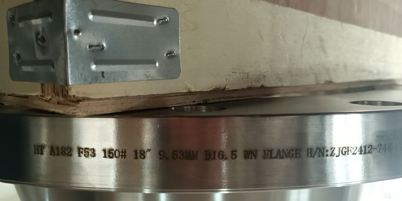
Marking | Grade, size, class, standard, heat number on the hub | Photographic record before packing |
Release | Final review of the document package | Certificate package issued to the customer |
Certification and traceability were the first reason the Argentine buyer gave for choosing this supply route, and it is the right instinct. In an audited oil and gas project a flange without a heat number is not a flange - it is an unresolved question. Every piece in this shipment carries full material certification to EN 10204 3.1 with heat-code traceability back to the melt, which is what makes the operational safety case and the later audit defensible.
Use an over-alloyed super duplex filler, keep the heat input and interpass temperature low, shield with argon plus nitrogen, and never apply post-weld heat treatment. The heat-affected zone is where super duplex welds fail, not the weld metal.
The filler choice surprises people. Matching filler sounds logical and is wrong: ER2209, the standard duplex wire, is under-alloyed for 2507 and produces weld metal with a PREN below the base metal. ER2594 is deliberately over-alloyed, with around 9.5 % nickel, so that the fast cooling of a weld still leaves enough austenite in the deposit. Adding 2-3 % nitrogen to the shielding gas does the same job for nitrogen loss across the arc.
Welding and installation rules for F53 weld neck flanges
Parameter | Requirement | Consequence of ignoring it |
Filler metal | ER2594 (AWS A5.9) / E2594 (AWS A5.4) | ER2209 gives weld metal below the base-metal PREN and a weak pitting site |
Shielding gas | Argon plus 2-3 % nitrogen | Nitrogen loss from the pool drops both strength and pitting resistance |
Preheat | Not required | Unnecessary heat pushes the assembly towards the embrittlement range |
Interpass temperature | Below 100-150 C | Time in the 600-1000 C window precipitates sigma in the HAZ |
Heat input | Controlled and within the qualified range | Too low gives excess ferrite; too high precipitates intermetallics |
Post-weld heat treatment | Prohibited | Stress relief sits inside the sigma and 475 C ranges |
Thermal cutting or grinding abuse | Avoid local overheating | A locally overheated spot becomes the initiation site |
Ferrite check | Typically 30-65 FN in the weld metal | Outside the band, either cracking or corrosion resistance suffers |
Bolt-up | Cross-pattern torque to the gasket manufacturer's value | Uneven load cracks a flat-face partner or crushes the gasket |
One practical point that saves rework: because the order mixes flat face and raised face, fitters should confirm the mating face before welding, not after. A weld neck flange that has been welded to the wrong partner cannot be recovered without cutting it out.
The grade and UNS number, the dimensional standard and series, size, bore schedule, class, facing, heat treatment, any PREN or NACE requirement, the testing you want, the certification level, and the destination. Leaving any one of those open is how a buyer receives material that cannot support the design.
· Material: ASTM A182 F53 / ASME SA-182 F53, UNS S32750, with EN 1.4410 if the project uses European designations.
· Product standard: ASME B16.5 for NPS 1/2 to 24, or ASME B16.47 with the series stated - Series A or Series B - for NPS 26 and above.
· Size, pressure class and bore: NPS, class, and the pipe schedule the bore must match, because weld neck bores are ordered to a schedule, not to a size.
· Facing: RF, FF or RTJ, with the finish specified - the concentric or spiral serrated finish that gasket makers assume is not automatic.
· Heat treatment: solution anneal at 1025-1125 C followed by water quench, with the furnace chart supplied and PWHT explicitly prohibited.
· Chemistry and PREN: full analysis to ASTM A182 plus PREN >= 40 calculated as %Cr + 3.3 x %Mo + 16 x %N, with the calculation shown on the certificate.
· Mechanicals: tensile, 0.2 % yield, elongation and hardness, with impact testing at -46 C added where the design minimum temperature requires it.
· Sour service: NACE MR0175 / ISO 15156-3 and the exact hardness limit, plus the H2S partial pressure, chloride, pH and temperature the flange must qualify against.
· Supplementary testing: ASTM A923 for intermetallic phase, ASTM G48 for pitting, ferrite measurement, and PMI on every piece.
· Certification: EN 10204 3.1 as standard, or 3.2 with third-party witness where the project requires it.
· Marking and packing: grade, size, class, standard, heat number and manufacturer's mark, with export packing and end protection for sea freight.
For buyers who want a worked example of how a complete documentation package looks, the S32750 pipe fittings shipment to Brazil and the Inconel 625 pipe shipment to Malaysia both show the same certification structure applied to different alloys.
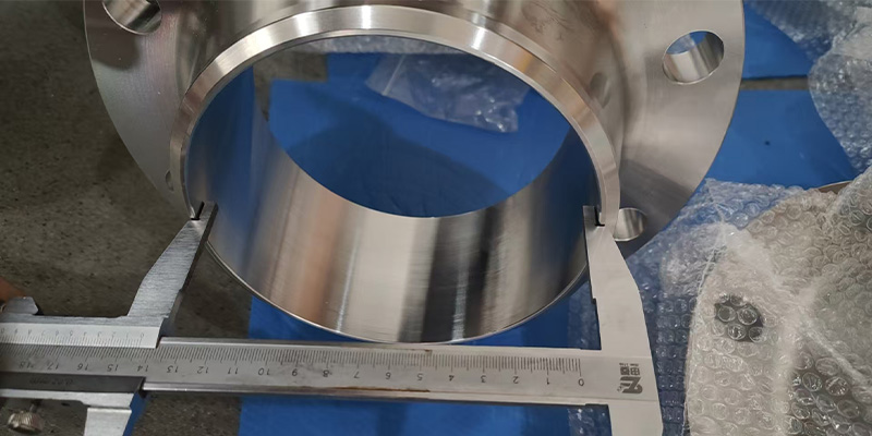
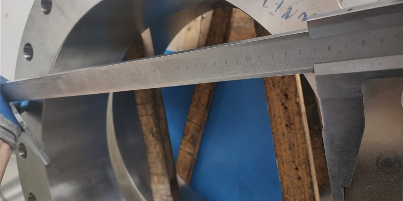
Each flange was marked on the hub with grade, size, class, standard and heat number, protected at the machined faces and bore, packed for sea freight, and dispatched with the certificate package matched piece by piece to the packing list.
Packing sounds like an afterthought until you have unloaded a container of machined super duplex and found a damaged raised face. The failure mode is specific: a nicked or scored sealing face on a flange that has travelled eight weeks by sea is a flange that gets rejected at incoming inspection, and the replacement takes another full manufacturing cycle. End protection, separation between pieces and a packing list that reconciles to the heat numbers are cheap insurance against that.
· Hub marking on every piece: grade F53, UNS S32750, size, class, standard, heat number and manufacturer's mark.
· Machined faces and bores protected against impact and contamination.
· Export-grade packing suitable for sea freight, with pieces separated and restrained against movement.
· Packing list reconciled to heat numbers so incoming inspection can match certificates to physical pieces without re-sorting.
· Certificate package issued with the shipment, not after it - EN 10204 3.1, furnace charts, dimensional reports and PMI records.
· Photographic record of marking and packing retained for traceability.
Three things: specify the standard and series, not just the size; write the heat treatment and hardness limits into the PO; and order the certificate package at the same time as the material. Those three steps remove almost every cause of a rejected super duplex delivery.
Argentina is a demanding market to supply because the projects are large, the schedules are tight and the audit trail is strict. The country's upstream capital is concentrated in one basin where less than 10 per cent of the formation has been developed, so the same procurement questions will keep coming: which grade, which standard, which certificate. Getting the specification right at the inquiry stage is worth more than any saving on unit price, because a rejected flange costs the full lead time again.
· Name the dimensional standard and series on every line. A 26 in flange is B16.47, and Series A and Series B do not bolt together.
· State the heat treatment explicitly - solution anneal, water quench, furnace chart supplied - and write that PWHT is prohibited.
· Fix the hardness limit if H2S is present. Do not rely on the product specification default when your operator specification is tighter.
· Order bore to a pipe schedule, not to a nominal size, or the weld neck will not match the pipe wall.
· Ask for PMI on every piece. It is the cheapest way to catch a mixed-heat delivery before it reaches the welding bay.
· Confirm the series and facing when you place the order, not when the container lands - both are unrecoverable at that point.
JN ALLOY supplies the whole super duplex piping class to one UNS number - S32750 pipe, weld neck flanges, round bar and plate and sheet - so a project can hold one material specification across the line. Contact the team with your size, class and facing list for a firm quote and lead time.
· Super duplex S32750 / F53 - grade hub
· What is super duplex stainless steel S32750?
· Properties of super duplex S32750
· Duplex 2507: uses, composition and properties
· Duplex and super duplex overview
· Weld neck flanges - product page
· Know about weld neck flanges
· S32750 for seawater desalination - technical guide
· Materials for water treatment
· Materials for marine engineering
· Best alloy for offshore oil and gas pipelines
· Incoloy 825 vs Hastelloy C276 for sour gas service
· S32750 pipe fittings shipped to Brazil
· 30 tons of Incoloy 800 pipe shipped to Kuwait
1. Fix the material designation. Write ASTM A182 F53 (UNS S32750) on the PO, together with the governing flange standard - ASME B16.5 for NPS 1/2 to 24, ASME B16.47 Series A or B for NPS 26 and above - and the required pressure class and facing.
2. Set the corrosion requirement in numbers. State PREN >= 40 and the calculation basis (Cr + 3.3 x Mo + 16 x N), plus any ASTM G48 critical pitting temperature requirement the service demands.
3. Define the heat treatment and forbid PWHT. Require solution annealing at 1025-1125 C followed by water quenching, with the furnace chart attached. State explicitly that post-weld heat treatment is not permitted and that no field heating above 300 C is allowed.
4. Add the sour-service clause if H2S is present. Name NACE MR0175 / ISO 15156-3, give the maximum hardness you accept for base metal, weld metal and HAZ, and give the H2S partial pressure, chloride content, pH and temperature of the service.
5. Specify the verification package. Require EN 10204 3.1 (or 3.2 with third-party witness), heat-code traceability, chemical analysis, tensile and hardness results, ferrite count, ASTM A923 where specified, and PMI on every piece.
6. Verify on receipt. Check the heat number against the certificate, confirm the marking matches the PO, run PMI on the Cr-Ni-Mo-N signature, and confirm the face finish and bore before the flange goes to the welding bay.
What is F53 material?
F53 is the ASTM A182 / ASME SA-182 grade designation for UNS S32750, a super duplex stainless steel also sold as alloy 2507, EN 1.4410 and X2CrNiMoN25-7-4. It contains 24-26 % chromium, 6-8 % nickel, 3-5 % molybdenum and 0.24-0.32 % nitrogen, giving a PREN of 40 or higher and a minimum yield strength of 550 MPa.
What does WN flange mean?
WN stands for weld neck. A weld neck flange has a long tapered hub that is butt-welded to the pipe, so the load path runs smoothly from pipe to flange. That geometry makes it the standard choice for high-pressure, cyclic and corrosive service, and it is the type specified on all 153 pieces in this shipment.
What is the difference between F53 and F51?
F51 (UNS S31803 / S32205, duplex 2205) has a PREN around 34-36 and a minimum yield of 450 MPa. F53 (UNS S32750, super duplex 2507) has a PREN of 40 or above and a minimum yield of 550 MPa. F53 costs roughly 30-50 % more but survives warm seawater, high-chloride brine and a much wider sour-service envelope.
What is the PREN of F53 and why does it matter?
PREN is calculated as %Cr + 3.3 x %Mo + 16 x %N and is 40 minimum for F53, typically 41-43. The number ranks resistance to chloride pitting. Offshore and high-chloride piping specifications commonly draw the line at PREN 40, which is exactly where super duplex separates from standard duplex.
Is F53 the same as 2507 or UNS S32750?
Yes. F53, UNS S32750, alloy 2507, EN 1.4410 and X2CrNiMoN25-7-4 all refer to the same 25Cr-7Ni-4Mo-N super duplex composition. F53 is the forging designation; S32750 is the UNS number; 2507 is the original producer trade name.
Can F53 flanges be used in seawater?
Yes. F53 is one of the standard materials for seawater duty, including cooling water, firewater and desalination brine. Its critical pitting temperature is far above that of 2205, and it resists crevice corrosion under gaskets and deposits where 316L would pit within months.
Is F53 suitable for sour service with H2S?
Yes, conditionally. UNS S32750 is listed in NACE MR0175 / ISO 15156-3, but it must be supplied solution annealed and water quenched, must meet the hardness limit your specification sets, and must operate inside the published envelope for H2S partial pressure, chloride, pH and temperature. The standard covers cracking only - pitting and general corrosion are assessed separately.
What hardness is required for F53 in sour service?
ASTM A182 permits up to 310 HBW (about 32 HRC) for the product, while many operator specifications tighten the requirement to 28 HRC and apply it to base metal, weld metal and the heat-affected zone. Because the two figures differ, the hardness limit must be stated explicitly on the purchase order rather than assumed.
What temperature range can F53 flanges be used over?
ASME B16.5 limits F53 to a maximum of 600 F (315 C) because of sigma-phase and 475 C embrittlement, and to a minimum of -20 F (-30 C) without impact testing. With Charpy testing to -46 C, super duplex is routinely used well below that. Many offshore specifications cap continuous service nearer 250 C.
Can super duplex F53 be post-weld heat treated?
No. Conventional stress-relief PWHT falls inside the temperature range where sigma phase and 475 C embrittlement form, so it is prohibited. The only permissible thermal treatment is a full solution anneal at 1025-1125 C followed by water quench, and that is applied to reworked material rather than to production welds.
What filler metal is used to weld F53?
ER2594 (AWS A5.9) for TIG and E2594 (AWS A5.4) for SMAW, with argon plus 2-3 % nitrogen as shielding gas. ER2209 must not be used - it is under-alloyed for 2507 and produces weld metal with insufficient pitting resistance. Interpass temperature is normally held below 100-150 C.
Which standard covers a 26-inch flange?
ASME B16.47, not B16.5. ASME B16.5 stops at NPS 24, so the 26-inch piece in this order is manufactured to B16.47 Series A (MSS SP-44 lineage) or Series B (API 605 lineage). The two series have different bolt circles and thicknesses and are not interchangeable, so the series must be stated on the inquiry.
What is the difference between a flat face and a raised face flange?
A raised face has a raised concentric ring that concentrates bolt load onto a narrow gasket; a flat face is machined flat across the whole sealing area and is used when the mating item is cast iron, GRP or another low-rigidity material. An FF flange and an RF flange must never be bolted together, because the raised ring will bend or crack the flat-face partner.
Why did the Argentine buyer choose weld neck flanges?
Because the tapered hub carries stress away from the weld and gives a full-penetration butt joint that can be radiographed, and because the smooth bore reduces turbulence and erosion in corrosive, solids-bearing fluids. For chloride and H2S service at Class 150 on 6 to 26 inch lines, a weld neck is the conservative and usually the Code-preferred choice.
What documents should come with an F53 flange order?
An EN 10204 3.1 mill certificate at minimum, showing heat number, full chemical analysis, tensile, yield, elongation and hardness, the solution-anneal temperature and quench method, ferrite content where specified, and PMI results. For critical service, EN 10204 3.2 with third-party witness is specified instead.
What is the lead time for F53 weld neck flanges?
Lead time depends on size, class and whether raw forging stock is in inventory. Common sizes below NPS 24 in Class 150 to 600 are usually the fastest; sizes above NPS 24, heavy wall hubs and third-party witnessed orders add time. Ask for a firm lead time against your actual size and class list rather than a general figure.
Does JN ALLOY supply F53 in other product forms?
Yes. The same UNS S32750 chemistry is supplied as pipe and tube to ASTM A790 / A789, buttweld fittings to ASTM A815 WPS32750, plate to ASTM A240, and bar to ASTM A276 / A479, so a whole piping class can be sourced to one UNS number.
How much does an F53 flange cost compared with 316L?
F53 typically costs 30-50 % more than duplex 2205 and several times more than 316L per kilogram. The comparison that matters is not unit price but installed life: in warm chloride or sour service a 316L flange can fail in months, so the cheaper option carries repeated replacement, downtime and leak risk.
What is Vaca Muerta?
Vaca Muerta is a Late Jurassic to Early Cretaceous shale formation roughly 2,900 m below the Neuquen Basin in northern Patagonia, Argentina. It supplies the majority of the country's crude and most of Neuquen's gas, and attracts more than 90 % of Argentina's upstream capital spending.
Why does Vaca Muerta need corrosion-resistant piping?
Because both the produced fluids and the water cycle attack carbon steel. Measured Vaca Muerta flowback rises from about 2,000 mg/L total dissolved solids to over 43,000 mg/L within a month - saltier than seawater - while disposal-zone brines are more saline still. Combined with H2S in parts of the basin, that puts plain carbon steel and 316L outside their safe envelope.
Can 316L be used instead of F53 in Argentine oil and gas service?
Only where chlorides are low and the metal stays cool. 316L has a PREN in the mid-20s and is vulnerable to chloride stress corrosion cracking above roughly 60 C. Once flowback, produced water or seawater is in the line, super duplex or a nickel alloy is the defensible choice.
How does F53 compare with Inconel 625 for the same service?
Inconel 625 resists higher chloride and sour severity and tolerates higher temperature, but it costs substantially more and has a lower yield strength in the annealed condition. F53 is the value choice where the environment sits inside the super duplex envelope; 625 is specified when it does not, or when elemental sulphur is present.
What should I put on an inquiry for F53 flanges?
Grade and UNS number, flange type, size and bore schedule, pressure class, facing (RF, FF or RTJ), the governing dimensional standard and series, quantity, heat treatment, any NACE or PREN requirement, testing such as ASTM A923 or G48, certification level, and the destination port.


