Views: 6 Author: Monica Publish Time: 2025-10-13 Origin: Site


ASTM B564 UNS N10276 flanges are pipe fittings manufactured from Hastelloy C276 in compliance with the ASTM B564 standard specification. This nickel-based alloy incorporates molybdenum, chromium, and tungsten, delivering exceptional corrosion resistance, particularly against pitting, crevice corrosion, and stress corrosion cracking.
Manufactured through forging, the ASTM B564 UNS N10276 flange exhibits mechanical properties including a minimum tensile strength of 690 MPa, a minimum yield strength of 275 MPa, and a minimum elongation of 40%. It can be fabricated into various types according to standards such as ASME B16.5, including butt-weld flanges, slip-on flanges, and blind flanges, to meet diverse pipeline connection requirements.

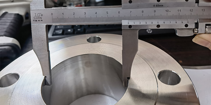
The dimensional specifications for ASTM B564 UNS N10276 (Hastelloy C276) flanges primarily follow general pipe flange standards such as ASME B16.5. Their dimensions are jointly determined by nominal bore (DN/NPS) and pressure rating (Class).
Due to the extensive range of pressure ratings and specifications, the table below summarizes key specification parameters, definitions, and their corresponding values across different pressure ratings.
Parameters | Specifications | Explanation | Standards |
Basics | Nominal Diameter (DN/NPS) | For example, DN15 (½“) to DN600 (24”) | ASME B16.5 |
Pressure Class | 150, 300, 400, 600, 900, 1500, 2500, etc. | ASME B16.5 | |
Key Connection Dimensions | Flange Outer Diameter (OD) | For example, DN100 (4") Class 150 flange has an outer diameter of approximately 228.6 mm | ASME B16.5 |
Bolt Circle Diameter | For example, DN100 (4") Class 150 is approximately 190.5 mm | ASME B16.5 | |
Bolt Hole Diameter | For example, DN100 (4") Class 150 is 19.1 mm | ASME B16.5 | |
Number of Bolt Holes | For example, DN100 (4") Class 150 has 8 | ASME B16.5 | |
Structural Dimensions | Flange Thickness | Increases with nominal diameter and pressure rating | ASME B16.5 |
Sealing Surface Dimensions (e.g., Raised Face RF Height/Diameter) | Clearly defined, e.g., raised face (RF) flange height and diameter | ASME B16.5 | |
Flange Types | Weld Neck Flange (WN) | Weld neck flange, suitable for high-pressure, high-temperature, and severe service conditions | ASME B16.5 |
Slip-On Flange (SO) | Pipe slides into flange bore for welding, facilitating installation | ASME B16.5 | |
Threaded Flange (Threaded) | Connects pipes via threaded connection, eliminating welding | ASME B16.5 | |
Socket Weld Flange (SW) | Pipe inserts into socket hole for welding | ASME B16.5 | |
Blind Flange (BL) | Used for sealing pipe ends | ASME B16.5 | |
Lapped Joint Flange (Lapped Joint) | Used with stub pipe fittings | ASME B16.5 |

Material Standards: ASTM B564 / ASME SB564
Dimension Standards:
ANSI/ASME B16.5
ASME B16.47 Series A & B
B16.48, BS4504, BS 10, EN-1092, DIN, etc.
Size Range: ½ inch (15 NB) to 48 inches (1200 NB), with some references indicating up to 60 inches
Pressure Ratings:
American Standard Series (Class): 150, 300, 600, 900, 1500, 2500
European Series (PN): PN6, PN10, PN16, PN25, PN40, PN64, etc.
Pipe Size (NPS) | Flange Outer Diameter (A) | Bolt Hole Center Circle Diameter (B) | Number of Bolt Holes (n) | Bolt Hole Diameter (C) | Flange Thickness (RF) |
1/2 | 3.50 in | 2.38 in | 4 | 0.62 in | 0.56 in |
1 | 4.25 in | 3.12 in | 4 | 0.62 in | 0.62 in |
2 | 6.00 in | 4.75 in | 4 | 0.75 in | 0.69 in |
4 | 9.00 in | 7.50 in | 8 | 0.75 in | 0.88 in |
8 | 15.00 in | 13.00 in | 8 | 0.88 in | 1.00 in |
12 | 19.00 in | 16.00 in | 12 | 1.00 in | 1.12 in |
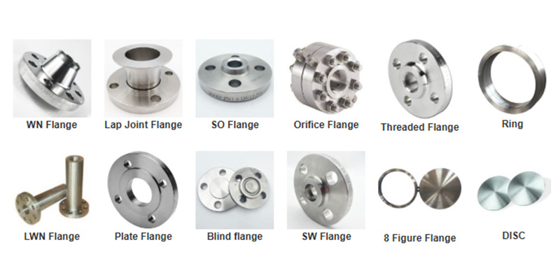
ASTM B564 UNS N10276 flanges come in various types to accommodate different pressures, connection methods, and installation requirements. The primary types are as follows:

Weld Neck Flange: Features a high-neck taper for butt-welding to piping. This design distributes stress from the flange neck to the pipe, offering superior resistance to mechanical fatigue and thermal stress cycling.
It is particularly suited for high-temperature, high-pressure, and fluctuating conditions, such as in high-pressure piping systems within petrochemical and power generation industries. Manufacturing typically follows standards like ASME B16.5.
Weld Neck Flange: Welded to the pipe's outer wall via a fillet weld. Compared to butt-weld flanges, it offers easier installation and lower cost, making it suitable for applications with moderate pressure ratings, frequent disassembly requirements, or limited space.
However, due to its shorter neck and different connection method, its pressure-bearing capacity and fatigue resistance are generally inferior to butt-weld flanges.
Socket Weld Flange: Pipes are inserted into the socket opening of the flange body, followed by external fillet welding. This design facilitates center alignment during installation and provides excellent sealing, commonly used in small-diameter high-pressure piping systems like instrument branch lines and sampling lines. However, potential root gaps at the joint make it unsuitable for applications prone to crevice corrosion.
Threaded Flanges: These achieve a completely weld-free assembly by directly screwing together internal threads with external pipe threads. This makes them an alternative to traditional welded flanges, particularly suitable for applications where hot work is prohibited, temporary piping, or connections involving certain special alloys. However, their sealing reliability may be compromised under conditions of severe vibration or thermal cycling.
Blind Flange: A solid flange with no center hole, primarily used to isolate or seal the end of a piping system or an opening after a valve for subsequent maintenance or system expansion. It is one of the highest pressure-rated flange types and is commonly used to isolate sections during pressure testing.
Loose Flanges: Used in combination with weld neck rings or flanged stub ends, where the flange ring can rotate freely. Advantages include easier bolt hole alignment and the ability to manufacture flanges from lower-grade materials for cost savings. They are particularly suitable for large-diameter pipelines requiring frequent disassembly or where alignment is difficult.
The weight of ASTM B564 UNS N10276 flanges is primarily determined by their DN/NPS, PN/Class, and construction. The table below provides weight values for flanges of various specifications based on common flange standards (such as ASME B16.5) and the density of Hastelloy.
The table below lists theoretical weight estimates for ASTM B564 UNS N10276 flanges under common nominal diameters and pressure ratings. All weights are in kilograms (kg).

Nominal Diameter (DN) | Pressure Rating (Class) | Flange Outer Diameter (OD) mm | Flange Thickness (C) mm | Weight
(kg) |
50 | 150 | 165 | 22 | 3.2 |
50 | 300 | 165 | 26 | 3.8 |
80 | 150 | 200 | 24 | 5.6 |
80 | 300 | 200 | 29 | 6.8 |
100 | 150 | 216 | 26 | 7.1 |
100 | 300 | 235 | 32 | 10.5 |
150 | 150 | 280 | 32 | 14.5 |
150 | 300 | 305 | 37 | 19.8 |
200 | 150 | 345 | 36 | 25.3 |
200 | 300 | 375 | 42 | 34.2 |
250 | 150 | 405 | 40 | 38.9 |
250 | 300 | 445 | 48 | 54.1 |
300 | 150 | 485 | 44 | 52.8 |
300 | 300 | 535 | 52 | 73.5 |
WN Flange
Lap Joint Flange
SO Flange
Orifice Flange
Threaded Flange
Ring
LWN Flange
Plate Flange
Blind flange
SW Flange
8 Figure Flange
Disc